Introduction
For industrial facilities reliant on thermal processes, generating high-pressure utility steam and hot water is an intensely resource-heavy operation. From running large-scale automated cleaning systems and chemical treatment tanks to operating continuous curing ovens, sterilization loops, and high-capacity dryers, modern processing plants depend heavily on industrial boilers to keep production moving.
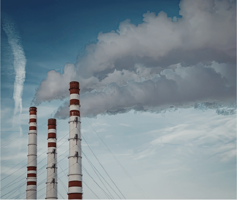
This heavy utility consumption directly impacts both your operating margins and your facility’s carbon profile. With global supply chains intensifying corporate sustainability audits and international trade frameworks expanding, lowering direct emissions from your utility house has become a practical necessity to maintain high-value client contracts, manage compliance costs, and protect your market position.
While transitioning to radical new technologies like green hydrogen or complete electrification is frequently discussed, these options are often held back by high capital expenditures, long payback horizons, and grid infrastructure delays.
A more immediate, commercially viable strategy is prioritizing thermal efficiency as a core decarbonization pillar.
In industrial steam and hot water systems, small operational adjustments yield predictable financial and environmental returns. This dynamic is driven by The 1% Decarbonization Rule: every 1% increase in your boiler’s thermal efficiency yields a corresponding 1% reduction in fuel consumption and greenhouse gas emissions. By capturing and recycling waste heat currently lost through your chimney—using proven flue gas heat recovery systems—your facility can lower its Scope 1 footprint while dropping its daily fuel expenses.
Framing Scope 1 Footprints in Industrial Operations
To optimize operational footprints, plant managers must address direct combustion sources. Under standard corporate carbon accounting protocols, manufacturing emissions are divided into three areas:
For industrial units running multi-shift or continuous 24/7 campaigns, the utility boiler house is a primary source of Scope 1 emissions. Fossil and biomass fuels are burned continuously to generate steam or hot water for process equipment and facility utility lines. The baseline carbon intensity of these thermal loops depends entirely on the chosen fuel supply.
Processing Fuel Profiles
|
Fuel Type |
Common Plant Application |
Carbon Intensity Context |
|
Heavy Fuel Oil (HFO) / Diesel |
Legacy utility infrastructure, backup steam generation |
High (~74–78 g CO2/MJ) |
|
Natural Gas |
Modern clean utility steam, direct-fired air heaters |
Lowest Fossil Fuel (~56 g CO2/MJ) |
|
Agro-Biomass (Briquettes/Pellets) |
Solid-fuel boilers, decentralized industrial clusters |
Low/Carbon Neutral (Biogenic)* |
Note: While agro-biomass combustion is legally considered carbon-neutral, localized material transportation, raw fuel storage handling, and poor burner optimization can still leave a severe environmental footprint if left unmonitored.
Mapping the Lost Energy Footprint
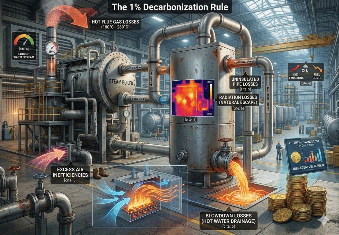
No industrial boiler transfers 100% of its combustion energy into the process line. Unchecked energy escapes at multiple points on the shop floor, and every unit of lost heat directly represents unneeded fuel burned and unnecessary greenhouse gases released:
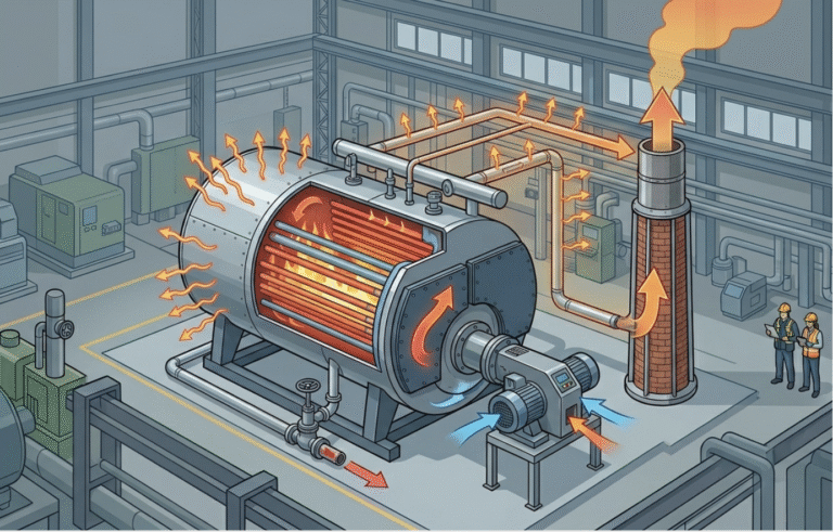
- Stack Losses (Flue Gas): The largest source of waste. High-temperature exhaust gases (180 degree celsius to 260 degree celsius are vented directly out the chimney, carrying valuable thermal energy away into the atmosphere.
- Blowdown Losses: Periodically draining boiling water to prevent mineral scale accumulation on internal tubes forces high-temperature energy out of the system.
- Excess Air Inefficiencies: Burners pull in extra air to ensure safe, complete combustion. If unmanaged, this extra air simply robs heat from the flame and carries it straight out the stack.
- Radiation Losses: Heat escaping naturally through the physical shell of uninsulated boilers and high-pressure steam distribution headers.
Typical System Energy Balance
| Loss Category | Fuel Input Share | Carbon & Operational Implication |
| Flue Gas (Stack) Loss | 10% – 20% | The primary cause of structural carbon and financial waste. |
| Excess Air Loss | 2% – 5% | Increases stack velocity, pulling useful heat out. |
| Radiation & Convection | 1% – 3% | Radiant heat loss requiring localized insulation mitigation. |
| Blowdown Loss | 1% – 3% | High-temperature fluid loss lowering net system efficiency. |
| Useful Process Energy | 70% – 82% | Net baseline boiler thermal efficiency. |
Woven Carbon Abatement: The 1% Rule
Flue gas contains two primary energy states: sensible heat (the physical temperature of the gas) and latent heat (the hidden vapor energy formed when fuel hydrogen burns). Flue gas heat recovery uses specialized inline heat exchangers to intercept this escaping mixture before it exits the facility stack.
By redirecting this energy back into your utility loops, you activate the 1% Decarbonization Rule:
The 1% Engineering Rule:
Reducing the boiler exhaust stack temperature by 20°C increases net thermal efficiency by 1%. This step drops absolute fuel spending by 1% and permanently avoids 1% of the facility’s Scope 1 emissions.
▼ 20°C Flue Gas Temp ──> ▲ 1% Boiler Efficiency ──> ▼ 1% Fuel Use & Scope 1 CO2.
This relationship ensures that decarbonization isn’t just an isolated addition at the end of the stack; it is directly woven into the facility’s daily fuel metrics. Using less fuel per unit of output automatically lowers the carbon intensity of your final manufactured goods or processed materials.
Scaled Field Scenarios
Scenario A: Gas-Fired Utility Setup
A facility operates a 6-ton natural gas steam boiler to run process loops and wash lines, with an annual fuel spend of $900,000 and a baseline footprint of 3,900 tons of CO2. By installing an inline economizer that drops exhaust temperatures by 60°C, efficiency climbs by 3%. This yields an immediate annual savings of $27,000 and permanently eliminates 117 metric tons of CO2 from the plant’s yearly audit profile.

Scenario B: High-Volume Solid-Fuel Industrial Site
A large facility utilizes localized agro-biomass (agricultural briquettes) to generate process steam for large-scale production lines, running an annual fuel budget of $2,500,000. Implementing an advanced multi-stage recovery system lowers stack temperatures by 80°C, lifting system performance by 4%. This cuts annual fuel expenses by $100,000 while reducing absolute biomass transport, storage space, and handling logistics by 4%.
Industrial Recovery Technologies
Choosing an appropriate system configuration depends on how the plant intends to recycle the reclaimed thermal energy back into its production utility loops.
1. Feedwater Economizers:
These finned-tube exchangers are placed directly within the exhaust duct to preheat incoming boiler feedwater. By raising the temperature of the water before it enters the boiler drum, the burner uses less fuel to generate steam, reducing the carbon footprint of the entire processing line.
2. Air Preheaters (APH):
These units transfer exhaust heat to the incoming combustion air drawn into the burner. Hotter intake air improves burner stability, accelerating combustion efficiency. They are especially effective for solid-fuel or biomass utility boilers that require rapid initial drying of incoming materials.
3. Condensing Economizers:
Built from highly corrosion-resistant stainless steel alloys, these systems cool flue gas below 55 degree celsius to capture latent phase-change energy. They unlock significant efficiency boosts (up to 10%–15%) and are ideal for generating the large volumes of hot wash water needed for surface preparation, chemical cleaning, CIP (Clean-In-Place) systems, and general plant utility lines.
Technology Selection Framework:
| System Type | Core Mechanism | Carbon Avoidance Profile | Best Fit |
| Standard Economizer | Preheats incoming feedwater | Steady 3% – 5% reduction | Continuous process steam loops |
| Air Preheater (APH) | Preheats intake burner air | Targeted 2% – 4% reduction | Solid fuel/biomass utility boilers |
| Condensing Unit | Reclaims latent phase energy | Maximum 8% – 15% reduction | High-volume low-temperature hot process water |
Real-World Applications & Case Studies
Case Study 1: Gas-Fired Process Line
- Application: An industrial processing facility running a 6-ton gas-fired boiler for fluid heating and equipment washing was venting exhaust at 215 degree celsius.
- Intervention: Retrofitted a standard finned-tube feedwater economizer.
- Result: Stack temperature dropped to 135 degree celsius, boosting boiler efficiency by 4.0%. The modification lowered annual fuel costs by $36,000 and reduced direct Scope 1 emissions by 145 metric tons of CO2 per year, achieving a full financial payback in 16 months.
Case Study 2: Solid-Fuel Manufacturing Plant
- Application: A manufacturing site utilized a solid-fuel boiler to run multi-stage thermal processing lines. Flue gas exited at 235 degree celsius, but high particulate fly ash regularly clogged standard heat exchangers.
- Intervention: Installed a specialized straight-tube economizer featuring an integrated automated compressed-air soot blower.
- Result: Safely lowered exhaust temperatures by 60 degree celsius, improving net efficiency by 3.0%. This intervention dropped raw fuel consumption by 180 tons annually, easing seasonal supply chain constraints and reducing localized carbon handling footprints without affecting production uptime.
Operational Readiness Checklist
Operations teams can utilize this checklist to quickly review if a facility is a candidate for a heat recovery upgrade:
☐ Operational Consistency: Does the boiler operate across multiple shifts? Continuous utilization patterns deliver the fastest financial and environmental paybacks.
☐ Thermal Window: Is the current stack temperature above 170 degree celsius? Higher baseline temperatures indicate more heat is available to reclaim.
☐ Fuel Composition Constraints: What fuel is burned? Gas allows for deep cooling; biomass and heavy oil require dedicated ash-cleaning systems and corrosion management.
☐ Thermal Matching: Is there an ongoing need for low-grade heat nearby? (e.g., incoming cold boiler feedwater, hot water wash systems, or adjacent industrial dryer air intakes).
☐ Spatial Clearance: Is there structural space available above or around the exhaust stack for retrofitting heat exchangers?
Conclusion: Compliance as a Competitive Edge
Integrating thermal efficiency is an actionable, high-impact step for processing and manufacturing facilities working toward decarbonization goals. By treating escaping exhaust gas as an active energy resource rather than a waste byproduct, plants can directly link emission reductions to immediate fuel cost savings.
Relying on the 1% Decarbonization Rule provides a clear framework for these upgrades: every 20°C drop in stack temperature reduces fuel costs and Scope 1 carbon outputs by 1%. When carbon accounting data is deeply integrated with daily process metrics, compliance transforms into a formidable competitive advantage—safeguarding high-value market access, strengthening critical supplier relationships with top-tier partners, and driving long-term industrial resilience on the global stage.